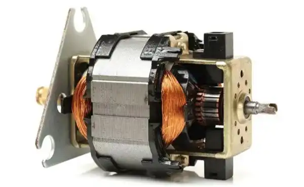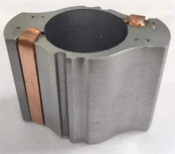

The motor stator is made of electrical steel laminations. Electrical steel, also known as silicon steel, is steel added with silicon. Adding silicon to steel can increase its resistance, improve the magnetic field penetration ability, and reduce the hysteresis loss of steel. Silicon steel is used for in many electrical applications of important electromagnetic fields, such as electrical stator/rotor and electrical machines, coils, magnetic coils and transformers.
Although the silicon in silicon steel helps to reduce corrosion, the main purpose of adding silicon is to improve the hysteresis loss of the steel. Adding silicon to steel makes the steel more efficient and faster at building and maintaining magnetic fields. Thus, silicon steel increases the efficiency and effectiveness of any device that uses steel as a magnetic core material.
The silicon steel sheet will generate a certain internal stress during the stamping process, which is harmful to the performance and mechanism design of the motor. The annealing process is one of the heat treatment processes to eliminate the changes in plasticity, strength, hardness and other properties caused by the microstructure of silicon steel. For electrical steel laminations for motor stator cores, the annealing process is most commonly used to relieve the stress of the silicon steel sheets around the edges of the laminations caused during the punching and punching process. Another common application in the motor industry involves annealing special alloys, such as cobalt or nickel, to optimize the electrical and mechanical properties of specially designed high-performance motors.
The punched silicon steel sheet is annealed before the stator lamination: the process is simple, and many different batches of silicon steel sheets can be annealed at one time, with high efficiency and low production cost.
Laminated stator annealing: if the stator laminations are welded or interlocked, they are not easy to loosen during annealing and can maintain good dimensional tolerances. However, if the stator is a bonded lamination or a loose lamination, a custom fixture must be designed to ensure that the laminations do not loosen during the annealing process, and the annealed laminations are then glued or coated for the next process. . This will increase production costs due to the design and input of additional batches of lamination fixtures for annealing.

The motor's stator and rotor cores are fabricated with thin sheets stacked together to minimize eddy current losses. To form a stable core, the laminations are glued together, baked and made sure the glue hardens. A general distinction is made between the technologies integrated in the punching process (interlocking, full-face bonding or point bonding) and those downstream of the punching process (welding, clamping, conventional bonding), the choice of joining technology depends on application, motor design and economic considerations.
Since manufacturing aspects such as interlocking or the location of the welds do not have to be considered, the backing self-adhesive technology allows complete design freedom and leads to ideal electrical engineering, with full bonding allowing compliance with the narrowest tolerances and good dimensional stability. Because lamination has no way of expanding. When heat is introduced during welding, it can cause tension in the core, which is not a problem during bonding. The lamination stack with the narrowest manufacturing tolerances improves heat dissipation by improving heat transfer between the laminations and the housing. This enables smaller cooling units, reducing cost and weight.

Of these technologies, bonding and heat treatment bring greater precision and reduced eddy current losses to bldc motors, and bonding is expected to eventually replace other methods as it results in thinner laminations that reduce the motor’s overall weight.